OSHA Requirements Machine Guarding – Quick Tips
Identify all the potential hazards in your workplace that require machine safeguarding and ensure they adhere to OSHA regulations.
Moving machine parts create workplace hazards and potential machinery-related injuries, making machine guards vitally important. All machines consist of three fundamental areas – the point of operation, the power transmission device and the operating controls. Machine safeguarding helps protect workers from preventable injuries in all three areas.
The Occupational Safety and Health Administration’s (OSHA’s) requirements for machine guarding are found in 29 Code of Federal Regulations (CFR) 1910 Subpart O, Machinery and Machine Guarding as detailed below;
- 211 — Definitions
- 212 — General requirements for all machines
- 213 — Woodworking machinery
- 214 — Cooperage machinery [Reserved]
- 215 — Abrasive wheel machinery
- 216 — Mills and calendars in the rubber/plastics industries
- 217 — Mechanical power presses
- 218 — Forging machines
- 219 — Mechanical power-transmission apparatus
General Requirements
29 CFR 1910.212(a)(1) states that one or more methods of machine guarding must be used to protect operators and other employees from hazards, including those created by point of operation, in-running nip points, rotating parts, flying chips and sparks.
Hazardous Mechanical Motions and Actions
Identifying hazards is the first step toward protecting workers and promoting safety in the workplace. The basic types of hazardous mechanical motions and actions are:
Examples of Hazardous Mechanical Motions
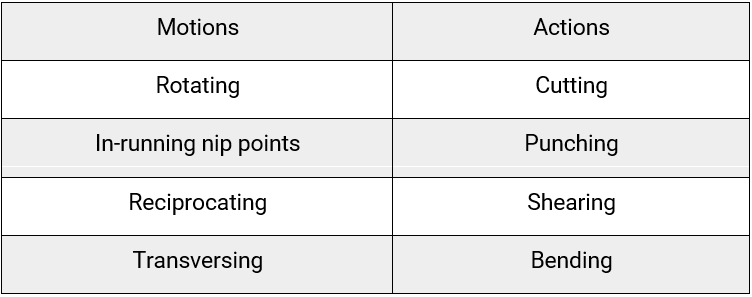
A rotating motion can be dangerous. Even smooth, slowly rotating shafts can grip clothing, and through mere skin contact, force an arm or hand into a dangerous position.
Collars, couplings, cams, clutches, flywheels, shaft ends, spindles and horizontal or vertical shafting are examples of common hazardous rotating mechanisms. The danger increases when bolts, nicks, abrasions and projecting keys or setscrews are exposed on rotating parts.
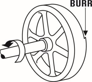
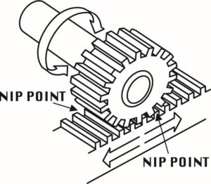
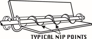
Rotating parts cause hazards such as in-running nip points. There are three main types of in-running nip points. Parts can rotate closely to each other in opposite directions while their axes are parallel to each other. When they run closely, the stock fed between two rolls produces a nip point. This danger is common on machines with intermeshing gears, rolling mills and calendars.

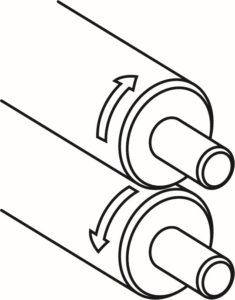

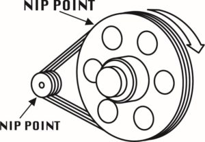
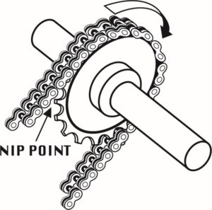
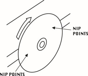
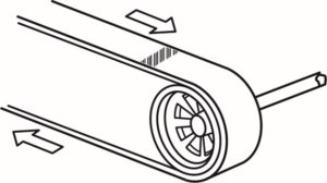
Rotating and tangentially moving parts also cause nip points. Potential hazards include the points of contact between a power transmission belt and its pulley, a chain and its sprocket, or a rack and pinion.
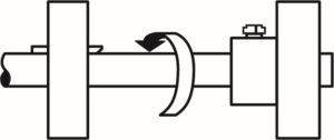
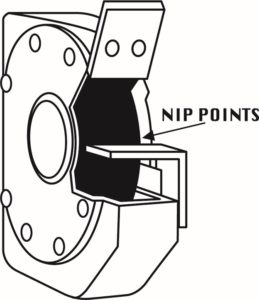
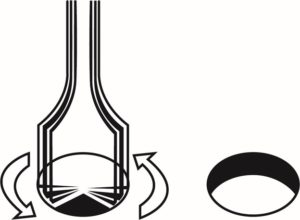
Nip points also occur between rotating and fixed parts, spoked hand wheels on flywheels, screw conveyors and the periphery of an abrasive wheel – and create shearing, crushing or abrading actions.
Reciprocating motions cause a back-and-forth or up-and-down action that can strike a worker or catch a worker between a moving and a stationary part.
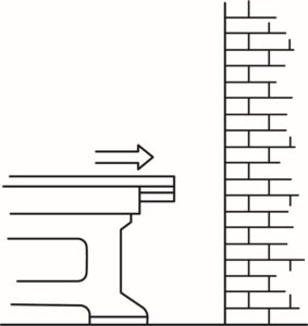
With transverse motion – movement in a straight continuous line – moving parts can catch or strike a worker in a pinch point or shear point.
Examples of Hazardous Mechanical Actions
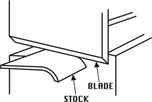
Cutting action hazards involve rotating, reciprocating or transverse motion, where finger, head and arm injuries can occur and where flying chips and scrap material can strike a worker’s eyes or face. Cutting actions are dangers with bandsaws, circular saws, and boring or drilling machines.
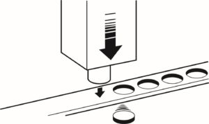
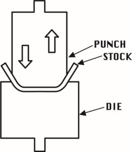
Punching action results when power is applied to a slide (ram) for the purpose of blanking, drawing or stamping metal or other materials. The danger occurs where stock is inserted, held and withdrawn by hand as with power presses.
Shearing action involves applying power to a shear or knife to trim or shear materials such as metal. The danger is where stock is inserted, held and withdrawn, as with hydraulically or pneumatically powered shears.
Bending action results when power is applied to a slide to draw or stamp metal or other material. This is a threat where stock is inserted, held and withdrawn, as with equipment such as power presses.
Requirements for Safeguards
Machine safeguards must meet these minimum general requirements:
- Prevent contact: The safeguard must prevent hands, arms or any other part of a worker’s body from contacting dangerous moving parts.
- Be secure: Workers should not be able to easily remove or tamper with the safeguard. Guards and safety devices should be made of durable materials that will withstand normal use. They must be firmly secured to the machine where possible or secured elsewhere if attachment to the machine is not possible.
- Protect from falling objects: The safeguard should ensure that no objects can fall into moving parts.
- Create no new hazards: A safeguard defeats its own purpose if it creates a hazard such as a shear point, a jagged edge or an unfinished surface. Edges of safeguards should be rolled or bolted so that they eliminate sharp edges.
- Create no interference: Any safeguard that impedes a worker from performing a job quickly and comfortably might be bypassed or disregarded. Proper safeguarding can enhance efficiency because it relieves a worker’s injury apprehensions.
- Allow safe lubrication: If possible, the machine should be able to be lubricated without removing the safeguard. Locating oil reservoirs outside the guard, with a line leading to the lubrication point, will reduce the need for the operator or maintenance worker to enter the hazardous area.
Types of Safeguarding
The type of operation, the size or shape of stock, the method of handling, the physical layout of the work area, the type of material and production requirements or limitations help determine the best method for safeguarding.
Safeguards are classified as either guards or devices.
Guards
Guards are barriers which prevent access to dangerous areas. There are four general types of guards:
- Fixed guards are permanent parts of a machine. These guards are preferable because they’re simple and permanent.
- Interlocked guards automatically shut off or disengage power through a tripping mechanism when it is opened or removed. The machine cannot cycle or start until the guard is replaced.
- Adjustable guards are useful because they accommodate various sizes of stock.
- Self-adjusting guards allow the opening of these barriers to be determined by the movement of the stock. As the operator moves the stock into the danger area, the guard is pushed away, providing an opening that only is large enough for the stock.
Devices
Safety devices perform several functions. They may stop a machine if any part of a body is inadvertently placed in the danger area. They may restrain or withdraw an operator’s hands from the danger area. They may require both hands on a control, therefore keeping both hands out of the danger area. They may also provide a synchronized barrier with the machines operating cycle to prevent entry into the danger area.
Devices include:
- Presence-sensing devices are divided into two groups. Photoelectrical devices use light sources and controls that can interrupt the machine’s operating cycle. Radiofrequency or capacitance devices use a radio beam that is part of the machine control circuit. When the capacitance field is broken, the machine will stop or not activate.
- Electromechanical sensing devices have a probe or contact bar that descends to a predetermined distance when the operator initiates the machine cycle. If there is an obstruction preventing it from descending to its full, predetermined distance, the control circuit does not start the machine cycle.
- Pullback devices use cables attached to the operator’s hands, wrists and/or arms. They are used primarily on machines with stroking-action hazards. When the slide/ram is up (between cycles), the operator has access to the points of operation. When the slide/ram begins to descend, a mechanical link automatically assures that the operator’s hands move away from the point of operation.
- Restraint (hold-back) devices allow the operator’s hands to travel only in a predetermined safe area and prevent the operator from reaching into a danger area. Cables or straps are attached to the operator’s hands and a fixed point. No extending or retracting actions are involved.
- Safety trip controls, such as pressure-sensitive body bars, safety tripods and safety tripwire cables, quickly deactivate a machine in an emergency.
- Two-hand controls require both hands and constant pressure on the controls for the machine to operate.
- Two-hand trip requires in sync application of both the operator’s control buttons to activate the machine cycle after which the hands are free. To be effective, both the controls and trips must be located so that the operator cannot use two hands or one hand and another part of their body to trip the machine.
- Gates are movable barriers that protect the operator at the point of operation before the machine cycle starts. To be effective, gates must be interlocked so that the machine will not begin a cycle unless the gate guard is in place.
Though not actual guards or devices, location and distance can keep employees safe by placing a machine in an infrequently traveled area or where it’s dangerous moving parts are not accessible. A thorough hazard analysis of each machine and situation is essential before using this safeguarding technique
Guard Construction
Guards designed and installed by the machine producer are desirable because they conform to the design and function of the machine, and they can be designed to strengthen the machine or to serve some additional functional purpose.
User-built guards are sometimes necessary and have some advantages. Often, with older machines, they are the only practical solution. They also might be the only choice for mechanical power transmission apparatuses in older plants, where machinery may not be powered by individual motor dries. User-built guards can be designed and built to fit unique and changing situations and can be installed on individual dies and feeding mechanisms. They also permit options for point-of-operation safeguards. When workers design and install machine guards, they develop a better knowledge of those guards and how they work.
However, there are some disadvantages. User-built guards might not conform well to the configuration and function of the machine and might be poorly designed or built.
Guard Materials
Metal, plastic, wood or any other material that is substantial enough to withstand impact and prolonged use are all used as construction materials for machine guards. In many circumstances, metal is the best material for guards. It might also be feasible to use plastic where higher machine visibility is required. Guards made of wood are generally not recommended because of their flammability and lack of durability and strength.
29 CFR 1910.219 Mechanical power-transmission apparatus, states that wood guards can be options in woodworking and chemicals industries, and in industries where vapors or gases or other conditions could deteriorate metal guards. Wood guards also may be used in construction work and in outdoor locations where extreme cold make metal guards undesirable. In all other industries, wood guards are not allowed, per 29 CFR 1910.219 (o)(2).
Summary
The list of possible machinery-related injuries created by moving machine parts is long – amputations, lacerations, crushing injuries, and abrasions, Machine safeguards are essential for protecting worker from these preventable injuries. Please click the link to review Grainger’s product line of machine guards.
Sources
29 CFR 1910 Subpart O
OSHA Machine Guarding E-Tool
Frequently Asked Questions
Q: What is the point of operation?
A: The point of operation is where work is performed on the material, such as cutting, shaping, boring, or forming of stock.
Q: When must the blades of a fan be guarded?
A: The blades of a fan must be guarded when the periphery of the blades is less than seven feet above the floor or working level. The guards must not have openings larger than one-half inch (29 CFR 1910.212(a)(5)).
The information contained in this article is intended for general information purposes only and is based on information available as of the initial date of publication. No representation is made that the information or references are complete or remain current. This article is not a substitute for review of current applicable government regulations, industry standards, or other standards specific to your business and/or activities and should not be construed as legal advice or opinion. Readers with specific questions should refer to the applicable standards or consult with an attorney.
Source: Grainger Know How – https://www.grainger.com/know-how